Iranian Classification Society Rules

< Previous | Contents | Next >
ANNEX 1 Test and Inspection of FRP Materials for Primary Structures
1. General for Test and Inspection
1.1 General
Tests and inspections not mentioned this Guidance is to be in accordance with Ch 3, Sec 28 of
Guidance for Approval of Manufacturing Process and Type Approval, etc.
1.2 Material testing machines
The testing machines used for the mechanical testing of materials to carry out according to this Guidance are to be those which are inspected and have the inspection certificates issued by the recognized organization.
1.3 Environmental conditions of test place
Except for cases specifically designated otherwise, the environmental conditions of test place are to be the standard conditions(temperature = 20±5 ℃, relative humidity = 65±20 %).
1.4 Verification of materials
The manufacturer is to take necessary steps to ensure the relationship between product and test sample or test specimen.
1.5 Retests
When a part of the test results fails to comply with the requirements while the rest items of test are proved satisfactory, retest may be carried out on the failed test items by taking test specimens two times the required number of test specimens. In this case, the test is considered to have passed when all results of retests satisfy the requirements. However, in case where tests are carried out on laminates and the laminates are renewed, all the tests required for laminates are to be carried out.
1.6 Test results
When the tests specified in this Guidance are carried out, the test record describing the following
(1) through (9) are to be submitted to the Society.
(1) Kind and brand name of raw materials tested
(2) The following raw materials used for the preparation of test specimens (excluding (1) above):
(A) Kind and brand name of fibreglass reinforcements and resins for laminating
(B) Kind and blending ratio of fillers
(C) Kind and blending ratio of curing agents and accelerators
(3) Moulding method and moulding conditions
(4) Selection method of test specimens
(5) Date of moulding of test specimens and test date
(6) Test place and environmental conditions of the test place
(7) Type of testing machine
(8) Shape and dimensions of test specimens
(9) Test results
![]()
2. Resins and Gelcoats for Laminating
2.1 Shapes and Selection of Test Specimens
The shape and selection of test specimens used for the are to be in accordance with Table 1.1.
tests of resins and gelcoats for laminating
Table 1.1 Resins and Gelcoats for Laminating (unit : mm)
Test item | Shape and size of test specimen | Quantity | Selection of test specimen, etc. |
Viscosity and thixotropy | Resins | As required | When resins are sampled, the contents of vessel are to be stirred well to make them homogeneous, and take test resins into a suitable dry and clean vessel of two times the necessary volume for test and a light-proof plug is. |
Gel time, minimum cure time and peak exothermic temperature | Resins | 50±1 g | |
Acid value | Resins | 1 g | |
Note 1. In the case of no-accelerated resins, the specified amount of accelerators is to be added and stirred according to the weight of the resins. | |||
2.2 Test Procedures
(1) Viscosity and thixotropy
(A) The test resins are to be as given in Table 1.1.
(B) Brookfield viscometer is to be used.
(C) The rotor and guard (or sleeve guard) chosen according to the predicted viscosity uid sample are to be mounted on the viscometer.
of the liq-
(D) The test liquid resins(25±0.5℃) after being stirred well are to be filled into the breaker to
a depth so that the reference mark on the rotor may be equal to the liquid level.
(E) After leaving still for approximately 5 minutes and then turning the rotor at a rotational
speed of 60 rpm for 3 minutes, the reading of the scale is to be taken. The viscosity is to be obtained by multiplying the reading by a coefficient determined according to the type of rotor used and rotational speed.
(F) After keeping still for another 5 minutes and then turning the rotor at a rotational speed of 6 rpm for 3 minutes, the reading is to be taken for obtaining the viscosity.
(G) The thixotropy is to be obtained by dividing the viscosity determined at the rotor run of 6 rpm by the viscosity at 60 rpm.
(H) The operations shown in (E) and (F) above are to be repeated for two times or more and the respective mean, values are to be regarded as the 'viscosity' and 'thixotropy.'
(I) The effective digit is to be 2-digit and the name of the viscometer and rotor number are to
be recorded.
(2) Gel time, minimum cure time and peak exothermic temperature
(A) The test resins are to be given in Table 1.1.
(B) The testing apparatus for hardening characteristics at room temperature is to be fixed in a thermostatic water bath(25±0.5℃)(See Fig 1.1).
![]()
24 Guidance relating to the Rules for the Classification of FRP Ships 2014
![]()
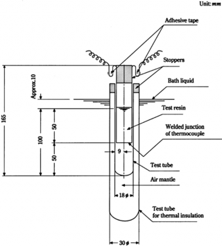
Fig 1.1 Testing Apparatus for Hardening Characteristics at Room Temperature
(C) The test resins are to be dipped in the thermostatic water bath and then the specified amount of sclerotics is to be added thereto when the temperature of the test resins reached
25±0.5℃, and the mixture is to be stirred evenly.
(D) The test resins added with sclerotics are to be filled into a test to a depth of 100 mm .
tube of 18 mm in diameter
(E)
The 18 mm diameter test tube is to be fixed in a test tube of the top surface of the test resins assumes approximately 10 mm
the thermostatic water bath.
30 mm in diameter so that below the liquid surface of
(F) The welded junction of thermocouple is to be placed at half the depth of the test resins and to be fixed at the centre of the test tube. However, a thermocouple ensleeved in a pro- tection tube or a thermistor may be used in place of the above thermocouple.
(G)
(H)
The time in minutes required for the test resins to reach a temperature of 30℃ from the
time when the sclerotic are mixed is to be taken as the gel time, and the time in minutes
required to reach the highest temperature after adding the sclerotics is to be taken as the minimum cure time, and the temperature indicated as the maximum temperature of the test
resin is to be taken as the peak exothermic temperature(℃).
Measurements are to be taken for two or more times, and the respective mean values are
to be regarded as the 'gel time', 'minimum cure time' and 'peak exothermic temperature'.
(I) The types and amounts of the sclerotics and accelerators are to be recorded.
(3) Acid value
(A) Take 1 g of the test resins, add it to about 10 ml of mixed solvent (mixture of 7 parts by mass of toluene (reagent) and 3 parts by mass of methyl alcohol (reagent)) and methyl alco-
hol (reagent), and stir the mixture well.
(B) Add the mixes indicator and titrate the solution with 0.1 molÕl (0.1N) ethyl alcoholic potas- sium hydroxide solution.
(C) When the colour of the solution turns from green into pale violet, take is as a poit of termination.
(D) The acid value is to be of the value obtained from the following formula.
![]()
Guidance relating to the Rules for the Classification of FRP Ships 2014 25
![]()
JǾĴÌſſlᾚ ÜĊ
where,
ſſl : Consumption of 0.1 molÕl (0.1C) ethyl alcoholic potassium hydroxide solution(ml )
ᾚ : Factor of 0.1 molÕl (0.1C) ethyl alcoholic potassium hydroxide
Ċ : Mass of test resins (g)
Note : The mixed indicator is the reagent obtained by adding 20 ml of distilled water to 0.1g of finely ground bromothymol blue and 0.1g of phenol red, and adding further 0.1 molÕl (0.1C) ethyl alcoholic potassium hidroxide solution thereto to the discolouring range while stirring it well, and by diluting it further with dis-
tilled water to a volume of 200 ml .
3. Fibre Reinforcements
3.1 Shape and Selection of Test Specimens
The shape and selection of test specimens accordance with Table 1.2.
used for tests of fibreglass reinforcements are to be in
Table 1.2 Fibre Reinforcements (unit : mm)
Test items | Shape and size of test specimen | Quantity | Sampling procedure, etc. |
Deviation | *1) *2)
| *1) 5 *2) 10 | Discard 30 mm from one longitudinal end and 30 mm from both transverse ends, and take a test sample of 1mĪ con- tinuously in the longitudinal direction(See Fig 1.2). After measuring weight of test sample *1), take a square(300×300) test specimen therefrom(See Fig 1.3). |
Rovings for spray-up are to have a length equivalent to ap- proximately 15g. | 5 | ||
Ratio in weight of binders | The same as in *2) | 5 | |
Tensile strength of fibreglass in roving cloth |
| warp direction : 5 weft direction : 5 | Test specimens are to be taken in warp and weft direction, respectively(See Fig 1.4). Finish it the shape as shown in Fig 1.5. |
![]()
26 Guidance relating to the Rules for the Classification of FRP Ships 2014
![]()
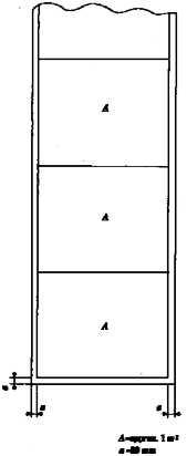
Fig 1.2 Selection of Test Specimens from Fibreglass Reinforcements
![]()
Guidance relating to the Rules for the Classification of FRP Ships 2014 27
![]()
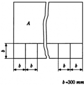
Fig 1.3 Selection of Test Specimens from Fibreglass Reinforcements
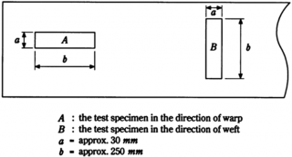
Fig 1.4 Selection of Tensile Test Specimens from Roving Cloth Reinforcements
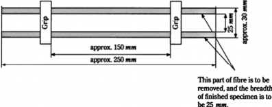
Fig 1.5 Tensile Test Sample of Roving Cloth
3.2 Test Procedures
The procedure of the tests given in Table 1.2 is to be in accordance with the following through (6).
(1) Design weight per unit area or unit length and the maximum deviation
(A) The test samples are to be in accordance with Table 1.2.
(B) The weight of the test sample is to be measured to the accuracy of 0.1 g.
(C) The deviation is to be of the value obtained from the following formula.
(a) Chopped mats and roving cloths
(1)
![]()
28 Guidance relating to the Rules for the Classification of FRP Ships 2014
![]()
For test sample of 1mĪ :
|BÌ Ň E |
ÜE× ÌLL
NŁŃ
For test sample of 300×300 mm Ī :
|BĪÕLǾLĶŇE |
Ü×EÌLL NŁŃ
where,
Ì
B : Weight of test sample of 1 m Ī(g)
Ī
B : Weight of test sample of 300×300 mm Ī(g)
E : Weight of test sample per 1 mĪ intended to be stated in the specification (hereinafter referred to as "normal weight")(g)
(b) Rovings
|ÌØ LLLBÕᾨŇE |
ÜE
× ÌLL NŁŃ
where,
ᾨ : Length of test sample(m )
E : Weight per 1,000m to be stated in specification(g)(hereinafter referred to as the "normal weight")
B : Weight of test sample(g)
(2) Ratio in weight of binder(including sizing agent)
(A) The test specimen are to be in accordance with Table 1.2.
(B) Each test specimen is to be heated in a heating furnace (625±25℃) for about 10 minutes to
burn out the binder or sizing agent, to be taken out from the furnace and to be left it to
cool down to the room temperature.
(C) The test sample in (B) above is to be weighed to the accuracy of 0.1 g.
(D) The ratio in weight of binders (including sizing agent) is to be of the value obtained from the following formula.
EL Ň EÌ × ÌLL NŁŃ ÜE L
where,
EL : Weight before heating(g)
EÌ : Weight after cooling(g)
(3) Tensile strength of fibreglass in roving cloth
(A) The test specimen are to be in accordance with Table 1.2.
(B) Tensile speed is to be 200 mmÕmi nǾ as the standard.
(C) When the test specimen failed or slipped at the grip of the testing machine,
value of this test sample is to be judged unacceptable. In such a case, a new is to be taken for additional test.
![]()
(D) The breaking load is to be taken as the tensile strength of fibreglass.
the measured test specimen
![]()
Guidance relating to the Rules for the Classification of FRP Ships 2014 29
![]()